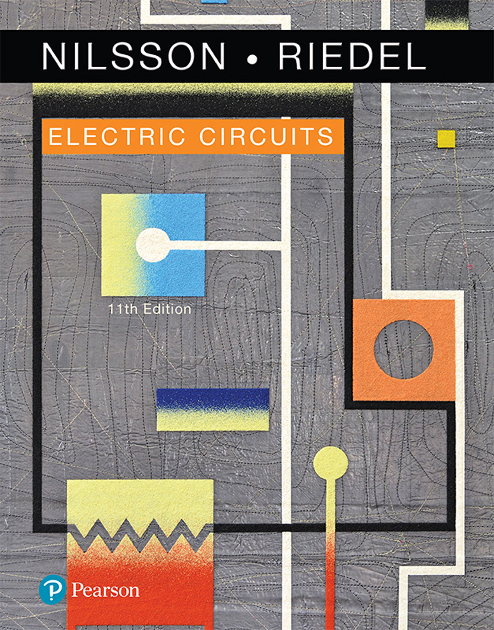
Electric Circuits 11th Edition by James Nilsson, Susan Riedel 0134747224 9780134747224
$50.00 Original price was: $50.00.$25.00Current price is: $25.00.
Electric Circuits 11th Edition by James W. Nilsson, Susan Riedel – Ebook PDF Instant Download/DeliveryISBN: 0134747224, 9780134747224
Full download Electric Circuits 11th Edition after payment.
Product details:
ISBN-10 : 0134747224
ISBN-13 : 9780134747224
Author: James W. Nilsson, Susan Riedel
This loose-leaf, three-hole punched version of the textbook gives you the flexibility to take only what you need to class and add your own notes–all at an affordable price. Note: You are purchasing the unbound Student Value Edition standalone product; Mastering Engineering does not come packaged with this content. Students, if interested in purchasing this title with Mastering Engineering, ask your instructor for the correct package ISBN and Course ID. For courses in Introductory Circuit Analysis or Circuit Theory. Challenge students to develop the insights of a practicing engineer The fundamental goals of the best-selling Electric Circuits, Student Value Edition, 11/e remain unchanged. The 11th Edition continues to motivate students to build new ideas based on concepts previously presented, to develop problem-solving skills that rely on a solid conceptual foundation, and to introduce realistic engineering experiences that challenge students to develop the insights of a practicing engineer. The 11th Edition represents the most extensive revision since the 5th Edition with every sentence, paragraph, subsection, and chapter examined and oftentimes rewritten to improve clarity, readability, and pedagogy—without sacrificing the breadth and depth of coverage that Electric Circuits is known for. Dr. Susan Riedel draws on her classroom experience to introduce the Analysis Methods feature, which gives students a step-by-step problem-solving approach.
Electric Circuits 11th table of contents:
Chapter 1 Circuit Variables
Chapter Contents
Chapter Objectives
1.1 Electrical Engineering: An Overview
Circuit Theory
Problem Solving
1.2 The International System of Units
1.3 Circuit Analysis: An Overview
1.4 Voltage and Current
1.5 The Ideal Basic Circuit Element
1.6 Power and Energy
Summary
Problems
Section 1.2
Section 1.4
Sections 1.5–1.6
Chapter 2 Circuit Elements
Chapter Contents
Chapter Objectives
2.1 Voltage and Current Sources
2.2 Electrical Resistance (Ohm’s Law)
2.3 Constructing a Circuit Model
2.4 Kirchhoff’s Laws
Kirchhoff’s Current Law
Kirchhoff’s Voltage Law
2.5 Analyzing a Circuit Containing Dependent Sources
Summary
Problems
Section 2.1
Sections 2.2–2.3
Section 2.4
Sections 2.1–2.5
Chapter 3 Simple Resistive Circuits
Chapter Contents
Chapter Objectives
3.1 Resistors in Series
3.2 Resistors in Parallel
3.3 The Voltage-Divider and Current-Divider Circuits
The Voltage-Divider Circuit
The Current-Divider Circuit
3.4 Voltage Division and Current Division
Voltage Division
Current Division
3.5 Measuring Voltage and Current
Analog Meters
Digital Meters
3.6 Measuring Resistance—The Wheatstone Bridge
3.7 Delta-to-Wye (Pi-to-Tee) Equivalent Circuits
Summary
Problems
Sections 3.1–3.2
Section 3.3
Section 3.4
Section 3.5
Section 3.6
Section 3.7
Sections 3.1–3.7
Chapter 4 Techniques of Circuit Analysis
Chapter Contents
Chapter Objectives
4.1 Terminology
Describing a Circuit—The Vocabulary
Simultaneous Equations—How Many?
4.2 Introduction to the Node-Voltage Method
4.3 The Node-Voltage Method and Dependent Sources
4.4 The Node-Voltage Method: Some Special Cases
The Concept of a Supernode
4.5 Introduction to the Mesh-Current Method
Applying the Mesh-Current Method
4.6 The Mesh-Current Method and Dependent Sources
4.7 The Mesh-Current Method: Some Special Cases
The Concept of a Supermesh
4.8 The Node-Voltage Method Versus the Mesh-Current Method
4.9 Source Transformations
4.10 Thévenin and Norton Equivalents
The Thévenin Equivalent
The Norton Equivalent
Using Source Transformations
4.11 More on Deriving the Thévenin Equivalent
4.12 Maximum Power Transfer
4.13 Superposition
Summary
Problems
Section 4.1
Section 4.2
Section 4.3
Section 4.4
Section 4.5
Section 4.6
Section 4.7
Section 4.8
Section 4.9
Section 4.10
Section 4.11
Section 4.12
Section 4.13
Sections 4.1–4.13
Chapter 5 The Operational Amplifier
Chapter Contents
Chapter Objectives
5.1 Operational Amplifier Terminals
5.2 Terminal Voltages and Currents
OP AMP Input Voltage Constraints
OP AMP Input Current Constraints
5.3 The Inverting-Amplifier Circuit
5.4 The Summing-Amplifier Circuit
5.5 The Noninverting-Amplifier Circuit
5.6 The Difference-Amplifier Circuit
The Difference Amplifier—Another Perspective
Measuring Difference-Amplifier Performance—The Common Mode Rejection Ratio
5.7 A More Realistic Model for the Operational Amplifier
Analyzing an Inverting-Amplifier Circuit Using a More Realistic Op Amp Model
Analyzing a Noninverting-Amplifier Circuit Using a More Realistic Op Amp Model
Summary
Problems
Sections 5.1–5.2
Section 5.3
Section 5.4
Section 5.5
Section 5.6
Sections 5.1–5.6
Section 5.7
Sections 5.1–5.7
Chapter 6 Inductance, Capacitance, and Mutual Inductance
Chapter Contents
Chapter Objectives
6.1 The Inductor
Current in an Inductor in Terms of the Voltage Across the Inductor
Power and Energy in the Inductor
6.2 The Capacitor
6.3 Series-Parallel Combinations of Inductance and Capacitance
Inductors in Series and Parallel
Capacitors in Series and Parallel
Inductor and Capacitor Symmetry
6.4 Mutual Inductance
The Procedure for Determining Dot Markings
6.5 A Closer Look at Mutual Inductance
A Review of Self-Inductance
The Concept of Mutual Inductance
Mutual Inductance in Terms of Self-Inductance
Energy Calculations
Summary
Problems
Section 6.1
Section 6.2
Section 6.3
Section 6.4
Section 6.5
Sections 6.1–6.5
Chapter 7 Response of First-Order RL and RC Circuits
Chapter Contents
Chapter Objectives
7.1 The Natural Response of an RL Circuit
Deriving the Expression for the Current
Deriving the Expressions for Voltage, Power, and Energy
The Significance of the Time Constant
7.2 The Natural Response of an RC Circuit
Deriving the Expression for the Voltage
7.3 The Step Response of RL and RC Circuits
The Step Response of an RL Circuit
Observations on the Step Response of an RL Circuit
The Step Response of an RC Circuit
7.4 A General Solution for Step and Natural Responses
7.5 Sequential Switching
7.6 Unbounded Response
7.7 The Integrating Amplifier
Summary
Problems
Section 7.1
Section 7.2
Section 7.3
Section 7.4
Section 7.5
Section 7.6
Section 7.7
Sections 7.1–7.7
Chapter 8 Natural and Step Responses of RLC Circuits
Chapter Contents
Chapter Objectives
8.1 Introduction to the Natural Response of a Parallel RLC Circuit
The General Solution of the Second-Order Differential Equation
8.2 The Forms of the Natural Response of a Parallel RLC Circuit
The Overdamped Response
The Underdamped Voltage Response
Characteristics of the Underdamped Response
The Critically Damped Voltage Response
8.3 The Step Response of a Parallel RLC Circuit
The Indirect Approach
The Direct Approach
8.4 The Natural and Step Response of a Series RLC Circuit
8.5 A Circuit with Two Integrating Amplifiers
Two Integrating Amplifiers with Feedback Resistors
Summary
Problems
Sections 8.1–8.2
Section 8.3
Section 8.4
Section 8.5
Sections 8.18.5
Chapter 9 Sinusoidal Steady-State Analysis
Chapter Contents
Chapter Objectives
9.1 The Sinusoidal Source
9.2 The Sinusoidal Response
9.3 The Phasor
Inverse Phasor Transform
9.4 The Passive Circuit Elements in the Frequency Domain
The V-I Relationship for a Resistor
The V-I Relationship for an Inductor
The V-I Relationship for a Capacitor
Impedance and Reactance
9.5 Kirchhoff’s Laws in the Frequency Domain
Kirchhoff’s Voltage Law in the Frequency Domain
Kirchhoff’s Current Law in the Frequency Domain
9.6 Series, Parallel, and Delta-to-Wye Simplifications
Combining Impedances in Series
Combining Impedances in Parallel
Delta-to-Wye Transformations
9.7 Source Transformations and Thévenin–Norton Equivalent Circuits
9.8 The Node-Voltage Method
9.9 The Mesh-Current Method
9.10 The Transformer
The Analysis of a Linear Transformer Circuit
Reflected Impedance
9.11 The Ideal Transformer
Exploring Limiting Values
Determining the Voltage and Current Ratios
Determining the Polarity of the Voltage and Current Ratios
Using an Ideal Transformer for Impedance Matching
9.12 Phasor Diagrams
Summary
Problems
Section 9.1
Section 9.2
Sections 9.3-9.4
Sections 9.5 and 9.6
Section 9.7
Section 9.8
Section 9.9
Sections 9.5-9.9
Section 9.10
Section 9.11
Section 9.12
Section 9.1-9.12
Chapter 10 Sinusoidal Steady-State Power Calculations
Chapter Contents
Chapter Objectives
10.1 Instantaneous Power
10.2 Average and Reactive Power
Power for Purely Resistive Circuits
Power for Purely Inductive Circuits
Power for Purely Capacitive Circuits
The Power Factor
Appliance Ratings
10.3 The rms Value and Power Calculations
10.4 Complex Power
10.5 Power Calculations
Alternate Forms for Complex Power
10.6 Maximum Power Transfer
The Maximum Average Power Absorbed
Maximum Power Transfer When ZL is Restricted
Summary
Problems
Sections 10.1–10.2
Section 10.3
Sections 10.4–10.5
Section 10.6
Sections 10.1–10.6
Chapter 11 Balanced Three-Phase Circuits
Chapter Contents
Chapter Objectives
11.1 Balanced Three-Phase Voltages
11.2 Three-Phase Voltage Sources
11.3 Analysis of the Wye-Wye Circuit
Terminology
Constructing a Single-Phase Equivalent Circuit
11.4 Analysis of the Wye-Delta Circuit
11.5 Power Calculations in Balanced Three-Phase Circuits
Average Power in a Balanced Wye Load
Reactive and Complex Power in a Balanced Wye Load
Power Calculations in a Balanced Delta Load
Instantaneous Power in Three-Phase Circuits
11.6 Measuring Average Power in Three-Phase Circuits
The Two-Wattmeter Method
Summary
Problems
Section 11.1
Section 11.2
Section 11.3
Section 11.4
Section 11.5
Section 11.6
Sections 11.1–11.6
Chapter 12 Introduction to the Laplace Transform
Chapter Contents
Chapter Objectives
12.1 Definition of the Laplace Transform
12.2 The Step Function
12.3 The Impulse Function
Describing the Impulse Function
Defining the Impulse Function and Its Sifting Property
Laplace Transform and Derivatives of the Impulse Function
12.4 Functional Transforms
12.5 Operational Transforms
Multiplication by a Constant
Addition and Subtraction
Differentiation
Integration
Translation in the Time Domain
Translation in the Frequency Domain
Scale Changing
12.6 Applying the Laplace Transform
12.7 Inverse Transforms
Partial Fraction Expansion: Proper Rational Functions
Partial Fraction Expansion: Distinct Real Roots of D(s)
Partial Fraction Expansion: Distinct Complex Roots of D(s)
Partial Fraction Expansion: Repeated Real Roots of D(s)
Partial Fraction Expansion: Repeated Complex Roots of D(s)
Partial Fraction Expansion: Improper Rational Functions
12.8 Poles and Zeros of F(s)
12.9 Initial- and Final-Value Theorems
Summary
Problems
Section 12.2
Section 12.3
Sections 12.4–12.5
Section 12.6
Section 12.7
Sections 12.8–12.9
Sections 12.1–12.9
Chapter 13 The Laplace Transform in Circuit Analysis
Chapter Contents
Chapter Objectives
13.1 Circuit Elements in the s Domain
A Resistor in the s Domain
An Inductor in the s Domain
A Capacitor in the s Domain
13.2 Circuit Analysis in the s Domain
13.3 Applications
13.4 The Transfer Function
The Location of Poles and Zeros of H(s)
13.5 The Transfer Function in Partial Fraction Expansions
Observations on the Use of H(s) in Circuit Analysis
13.6 The Transfer Function and the Convolution Integral
The Concepts of Memory and the Weighting Function
13.7 The Transfer Function and the Steady-State Sinusoidal Response
13.8 The Impulse Function in Circuit Analysis
Switching Operations
Capacitor Circuit
Impulsive Sources
Summary
Problems
Section 13.1
Section 13.2
Section 13.3
Sections 13.4–13.5
Section 13.6
Section 13.7
Section 13.8
Sections 13.1–13.8
Chapter 14 Introduction to Frequency Selective Circuits
Chapter Contents
Chapter Objectives
14.1 Some Preliminaries
14.2 Low-Pass Filters
The Series RL Circuit—Qualitative Analysis
Defining the Cutoff Frequency
The Series RL Circuit—Quantitative Analysis
A Series RC Circuit
Relating the Frequency Domain to the Time Domain
14.3 High-Pass Filters
The Series RC Circuit—Qualitative Analysis
The Series RC Circuit—Quantitative Analysis
14.4 Bandpass Filters
Center Frequency, Bandwidth, and Quality Factor
The Series RLC Circuit—Qualitative Analysis
The Series RLC Circuit—Quantitative Analysis
Relating the Frequency Domain to the Time Domain
14.5 Bandreject Filters
The Series RLC Circuit—Qualitative Analysis
The Series RLC Circuit—Quantitative Analysis
Summary
Problems
Section 14.2
Section 14.3
Section 14.4
Section 14.5
Sections 14.1–14.5
Chapter 15 Active Filter Circuits
Chapter Contents
Chapter Objectives
15.1 First-Order Low-Pass and High-Pass Filters
A Note About Frequency Response Plots
15.2 Scaling
The Use of Scaling in the Design of Filters
15.3 Op Amp Bandpass and Bandreject Filters
15.4 Higher-Order Op Amp Filters
Cascading Identical Filters
Butterworth Filters
Butterworth Filter Circuits
The Order of a Butterworth Filter
Butterworth High-Pass, Bandpass, and Bandreject Filters
15.5 Narrowband Bandpass and Bandreject Filters
Summary
Problems
Section 15.1
Section 15.2
Section 15.3
Section 15.4
Section 15.5
Sections 15.1–15.5
Chapter 16 Fourier Series
Chapter Contents
Chapter Objectives
16.1 Fourier Series Analysis: An Overview
16.2 The Fourier Coefficients
16.3 The Effect of Symmetry on the Fourier Coefficients
Even-Function Symmetry
Odd-Function Symmetry
Half-Wave Symmetry
Quarter-Wave Symmetry
16.4 An Alternative Trigonometric Form of the Fourier Series
16.5 An Application
An Application of the Direct Approach to the Steady-State Response
16.6 Average-Power Calculations with Periodic Functions
16.7 The rms Value of a Periodic Function
16.8 The Exponential Form of the Fourier Series
16.9 Amplitude and Phase Spectra
Summary
Problems
Sections 16.1–16.2
Section 16.3
Section 16.4
Section 16.5
Section 16.6
Section 16.7
Section 16.8
Section 16.9
Sections 16.1–16.9
Chapter 17 The Fourier Transform
Chapter Contents
Chapter Objectives
17.1 The Derivation of the Fourier Transform
17.2 The Convergence of the Fourier Integral
17.3 Using Laplace Transforms to Find Fourier Transforms
17.4 Fourier Transforms in the Limit
The Fourier Transform of a Signum Function
The Fourier Transform of a Unit Step Function
The Fourier Transform of a Cosine Function
17.5 Some Mathematical Properties
17.6 Operational Transforms
Multiplication by a Constant
Addition (Subtraction)
Differentiation
Integration
Scale Change
Translation in the Time Domain
Translation in the Frequency Domain
Modulation
Convolution in the Time Domain
Convolution in the Frequency Domain
17.7 Circuit Applications
17.8 Parseval’s Theorem
Demonstrating Parseval’s Theorem
Interpreting Parseval’s Theorem
Summary
Problems
Sections 17.1 17.2
Sections 17.3–17.5
Section 17.6
Section 17.7
Section 17.8
Chapter 18 Two-Port Circuits
Chapter Contents
Chapter Objectives
18.1 The Terminal Equations
18.2 The Two-Port Parameters
Relationships Among the Two-Port Parameters
Reciprocal Two-Port Circuits
18.3 Analysis of the Terminated Two-Port Circuit
The Six Characteristics in Terms of the z Parameters
18.4 Interconnected Two-Port Circuits
Summary
Problems
Sections 18.1–18.2
Section 18.3
Section 18.4
Sections 18.1–18.4
People also search for Electric Circuits 11th:
fundamentals of electric circuits 7th edition
sadiku fundamentals of electric circuits
introduction to electric circuits
fundamentals of electric circuits 7th edition solutions
fundamentals of electric circuits solutions
Tags: Electric Circuits, James Nilsson, Susan Riedel, Mastering Engineering
You may also like…
Engineering - Electrical & Electronic Engineering
Fundamentals of electric circuits Sixth Edition Alexander Charles K
Engineering
Electric Circuits 7th edition by Mahmood Nahvi, Joseph Edminister 1260011975 9781260011975
History & Research
Engineering
Engineering - Electrical & Electronic Engineering
Engineering - Electrical & Electronic Engineering
Electric Circuits 10th Edition by James Nilsson, Susan Riedel 0133760030 9780133760033
Engineering - Electrical & Electronic Engineering
Engineering - Electrical & Electronic Engineering
Electric Circuits [11th Ed] Instructor’s Solution Manual 11th Edition James W. Nilsson
Engineering - Electrical & Electronic Engineering



![Electric Circuits [11th Ed] Instructor’s Solution Manual 11th Edition James W. Nilsson](https://textbookfull.com/wp-content/uploads/2024/04/electric-circuits-11th-ed-instructors-solution-manual-7249250-247x296.jpg)
