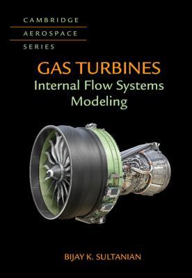
Gas Turbines Internal Flow Systems Modeling 1st edition by Bijay Sultanian 1316766989 9781316766989
$50.00 Original price was: $50.00.$25.00Current price is: $25.00.
Gas Turbines Internal Flow Systems Modeling 1st edition by Bijay Sultanian – Ebook PDF Instant Download/DeliveryISBN: 1316766989, 9781316766989
Full download Gas Turbines Internal Flow Systems Modeling 1st edition after payment.
Product details:
ISBN-10 : 1316766989
ISBN-13 : 9781316766989
Author: Bijay Sultanian
This long-awaited, physics-first and design-oriented text describes and explains the underlying flow and heat transfer theory of secondary air systems. An applications-oriented focus throughout the book provides the reader with robust solution techniques, state-of-the-art three-dimensional computational fluid dynamics (CFD) methodologies, and examples of compressible flow network modeling. It clearly explains elusive concepts of windage, non-isentropic generalized vortex, Ekman boundary layer, rotor disk pumping, and centrifugally-driven buoyant convection associated with gas turbine secondary flow systems featuring rotation. The book employs physics-based, design-oriented methodology to compute windage and swirl distributions in a complex rotor cavity formed by surfaces with arbitrary rotation, counter-rotation, and no rotation. This text will be a valuable tool for aircraft engine and industrial gas turbine design engineers as well as graduate students enrolled in advanced special topics courses.
Gas Turbines Internal Flow Systems Modeling 1st table of contents:
1 Overview of Gas Turbines for Propulsion and Power Generation
1.0 Introduction
1.1 Primary Flow: Energy Conversion
1.2 Internal Flow System (IFS)
1.2.1 Key Components
1.2.2 Efficiency Impact on Gas Turbine Components
1.2.3 Penalty on Engine Cycle Performance
1.3 Physics-Based Modeling
1.4 Robust Design Methodology
1.4.1 Monte Carlo Simulation
1.4.2 Response Surface Modeling
1.5 Concluding Remarks
Worked Examples
Problems
References
Bibliography
2 Review of Thermodynamics, Fluid Mechanics, and Heat Transfer
2.0 Introduction
2.1 Thermodynamics
2.1.1 The First Law of Thermodynamics
2.1.1.1 Enthalpy
2.1.2 The Second Law of Thermodynamics
2.1.2.1 Entropy
2.1.3 Thermodynamic Cycles
2.1.4 Isentropic Efficiency
2.1.5 Polytropic Efficiency
2.2 Fluid Mechanics
2.2.1 Secondary Flows
2.2.2 Vorticity and Vortex
2.2.3 Sudden Expansion Pipe Flow With and Without Swirl
2.2.4 Sudden Contraction Pipe Flow: Vena Contracta
2.2.5 Stream Thrust and Impulse Pressure
2.2.6 Control Volume Analyses of Conservation Laws
2.2.6.1 Mass Conservation (Continuity Equation)
2.2.6.2 Linear Momentum Equation
2.2.6.3 Angular Momentum Equation
2.2.6.4 Energy Equation
2.2.6.5 Entropy Equation
2.2.7 Euler’s Turbomachinery Equation
2.2.7.1 Rothalpy
2.2.7.2 An Alternate Form of the Euler’s Turbomachinery Equation
2.2.7.3 Total Pressure and Total Temperature in Stator and Rotor Reference Frames
2.2.8 Compressible Flow with Area Change, Friction, Heat Transfer, Rotation, and Normal Shocks
2.2.8.1 Isentropic Flow
2.2.8.2 Mass Flow Functions
2.2.8.3 Impulse Functions
2.2.8.4 Normal Shock Function
2.2.8.5 Isentropic Flow with Area Change
2.2.8.6 Isentropic Flow with Rotation
2.2.8.7 Nonisentropic Flow with Friction: Fanno Flow
2.2.8.8 Nonisentropic Flow with Heat Transfer: Rayleigh Flow
2.2.8.9 Nonisentropic Flow: Normal Shock
2.2.9 Navier-Stokes Equations
2.2.9.1 Inertial Reference Frame: Cartesian Coordinates
2.2.9.2 Inertial Reference Frame: Cylindrical Coordinates
2.2.9.3 Noninertial Reference Frame: Cylindrical Coordinates with Constant Rotation
2.2.9.4 Rotating Couette Flow
2.2.9.5 Taylor-Proudman Theorem
2.2.9.6 Ekman Boundary Layers
2.3 Internal Flow
2.3.1 Isentropic and Nonisentropic Vortices: Pressure and Temperature Changes
2.3.1.1 Isentropic Free Vortex
2.3.1.2 Isentropic Forced Vortex
2.3.1.3 Isothermal Forced Vortex
2.3.1.4 Nonisentropic Generalized Vortex
2.3.2 Windage versus Vortex Temperature Change
2.3.3 Loss Coefficient versus Discharge Coefficient
2.4 Heat Transfer
2.4.1 Conduction
2.4.1.1 One-Dimensional Steady Heat Conduction
2.4.1.2 One-Dimensional Unsteady Heat Conduction
2.4.2 Convection
2.4.2.1 Adiabatic Wall Temperature
2.4.2.2 Forced Convection over Isothermal Walls
2.4.3 Radiation
2.4.4 Multimode Heat Transfer
2.4.4.1 Electrical Analogy and Thermal Resistances
2.4.4.2 Coupling between Heat Transfer and Work Transfer in a Rotating Duct Flow
2.4.5 Numerical Heat Transfer
2.4.5.1 Conjugate Heat Transfer
2.5 Concluding Remarks
Worked Examples
Problems
References
Bibliography
3 1-D Flow and Network Modeling
3.0 Introduction
3.1 1-D Flow Modeling of Components
3.1.1 Duct with Area Change, Friction, Heat Transfer, and Rotation
3.1.1.1 Mass Conservation (Continuity Equation)
3.1.1.2 Linear Momentum Equation
3.1.1.3 Energy Equation
3.1.1.4 Internal Choking and Normal Shock Formation
3.1.1.5 Flexibility of Duct Flow Modeling
3.1.2 Orifice
3.1.2.1 Sharp-Edged Orifice
3.1.2.2 Generalized Orifice
3.1.3 Vortex
3.2 Description of a Flow Network: Elements and Junctions
3.2.1 Element
3.2.2 Internal Junction
3.2.3 Boundary Junction
3.3 Compressible Flow Network Solution
3.3.1 Initial Solution Generation
3.3.2 Determination of Element Flow Direction
3.3.3 Newton-Raphson Method
3.3.4 Modified Newton-Raphson Method
3.4 Concluding Remarks
Worked Examples
Problems
Project
References
Bibliography
4 Internal Flow around Rotors and Stators
4.0 Introduction
4.1 Rotor Disk
4.1.1 Free Disk Pumping
4.1.2 Disk Pumping Beneath a Forced Vortex
4.1.3 Rotor Disk in an Enclosed Cavity
4.2 Cavity
4.2.1 Rotor-Stator Cavity with Radial Outflow
4.2.2 Rotor-Stator Cavity with Radial Inflow
4.2.3 Rotating Cavity with Radial Outflow
4.2.4 Rotating Cavity with Radial Inflow
4.3 Windage and Swirl Modeling in a General Cavity
4.3.1 Arbitrary Cavity Surface Orientation: Conical and Cylindrical Surfaces
4.3.2 Bolts on Stator and Rotor Surfaces
4.4 Compressor Rotor Cavity
4.4.1 Flow and Heat Transfer Physics
4.4.2 Heat Transfer Modeling with Bore Flow
4.4.3 Heat Transfer Modeling of Closed Cavity
4.5 Preswirl System
4.5.1 Flow and Heat Transfer Modeling
4.6 Hot Gas Ingestion: Ingress and Egress
4.6.1 Physics of Hot Gas Ingestion
4.6.2 1-D Modeling
4.6.2.1 Single-Orifice Model
4.6.2.2 Multiple-Orifice Spoke Model
4.7 Axial Rotor Thrust
4.7.1 Computation of Axial Thrust on Blades
4.7.2 Computation of Axial Thrust on Rotor Disks
4.8 Concluding Remarks
Worked Examples
Problems
Projects
References
Bibliography
5 Labyrinth Seals
5.0 Introduction
5.1 Straight-Through and Stepped-Tooth Designs
5.1.1 Flow Physics
5.1.2 Leakage Mass Flow Rate
5.2 Tooth-by-Tooth Modeling
5.2.1 Orifice-Cavity Model
5.3 Concluding Remarks
Worked Examples
Project
References
Bibliography
6 Whole Engine Modeling
6.0 Introduction
6.1 Multiphysics Modeling of Engine Transients
6.2 Nonlinear Convection Links
6.2.1 Linear versus Nonlinear Convection Links
6.2.2 Nonlinear Convection Link in a Multisided Duct
6.2.2.1 Without Internal Heat Generation
6.2.2.2 With Uniform Internal Heat Generation
6.2.3 Multisurface Forced Vortex Convection Link with Windage
6.2.4 Junction of Convection Links
6.3 Role of Computational Fluid Dynamics (CFD)
6.3.1 Radially Inward Flow in a Compressor Rotor Drum Cavity
6.4 CFD Methodology
6.4.1 Governing Conservation Equations
Continuity equation:
Momentum equations:
Energy equation:
Chemical species conservation equation:
The common equation form:
6.4.2 Turbulence Modeling
6.4.2.1 Reynolds Equations: The Closure Problem
6.4.2.2 Prandtl Mixing-Length Model
6.4.2.3 One-Equation k-L Model
6.4.2.4 Two-Equation k-? Model (BVM)
6.4.2.5 Reynolds Stress Transport Model (RSTM)
6.4.2.6 Algebraic Stress Model (ASM)
6.4.3 Boundary Conditions
6.4.3.1 Inlet and Outlet Boundary Conditions
6.4.3.2 Wall Boundary Conditions: The Wall-Function Treatment
6.4.3.3 Alternative Near-Wall Treatments
6.4.4 Selection of a Turbulence Model
6.4.4.1 Turbulent Flow in a Noncircular Duct
6.4.4.2 Turbulent Flow in a Sudden Pipe Expansion
6.4.4.3 Swirling Turbulent Flow in a Sudden Pipe Expansion
6.4.4.4 Turbulent Flow and Heat Transfer in a Rotor Cavity
6.4.5 Physics-Based Postprocessing of CFD Results
6.4.5.1 Large Control Volume Analysis of CFD Results
6.4.5.2 Entropy Map Generation for Identifying Lossy Regions
6.5 Thermomechanical Analysis
6.5.1 Thermal Finite Element Analysis
6.5.2 Thermomechanical Finite Element Analysis
Step 1: Element Shape Function
Step 2: Element Strain-Displacement Equations
Step 3: Element Stress-Displacement Equations
Step 4: Element Equilibrium Equations Using Rayleigh-Ritz Method
6.6 Validation with Engine Test Data
6.7 Concluding Remarks
People also search for Gas Turbines Internal Flow Systems Modeling 1st:
gas turbine internal flow systems modeling pdf
how does a natural gas turbine work
how much does a gas turbine cost
gas turbine flow meter
gas turbine engine inlet flow distortion guidelines
Tags: Gas Turbines, Internal Flow, Systems Modeling, Bijay Sultanian
You may also like…
Science (General)
Engineering
Technique - Energy
Engineering
Modeling, Control, and Optimization of Natural Gas Processing Plants 1st Edition William A. Poe
Computers - Applications & Software


