
Ground Characterization and Structural Analyses for Tunnel Design 1st Edition by Benjamin Celada, Bieniawski 9781351168465 1351168460


Original price was: $50.00.$25.00Current price is: $25.00.
Ground Characterization and Structural Analyses for Tunnel Design 1st Edition by Benjamin Celada, Bieniawski – Ebook PDF Instant Download/Delivery: 9781351168465, 1351168460
Full download Ground Characterization and Structural Analyses for Tunnel Design 1st Edition after payment
Product details:
• ISBN 10:1351168460
• ISBN 13:9781351168465
• Author:Benjamin Celada, Bieniawski
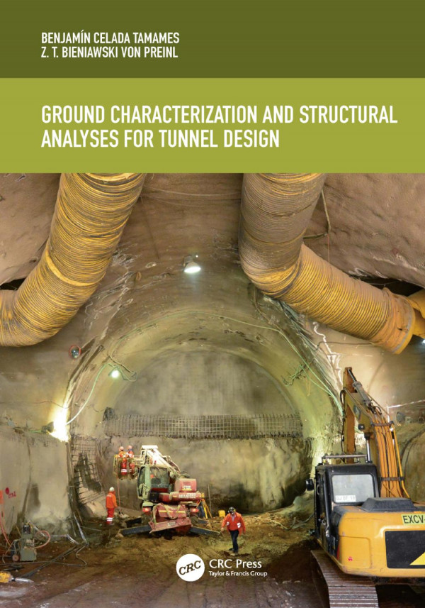
Ground Characterization and Structural Analyses for Tunnel Design
This practical and design-oriented book focuses on ground characterization and structural calculation, as part of the active structural design methodology. With a focus on rock tunnelling it offers a comprehensive rather than a topic-based perspective, deriving sound tunnel design criteria and methods from basic principles. Ground characterization includes excavations, site investigation, and in situ stress determination, culminating in geotechnical classifications. The book then deals with various construction methods and their appropriate calculations, which range from constitutive models for the stress-strain behaviour of an excavation and tunnel support elements to a full stress–strain analysis methodology. The heavily practical approach of the book draws on the authors’ twenty years of tunnelling experience in Spain and South America. It will help any young or established professional who wants to develop a career in the underground field across both civil engineering and geology. As it incorporates the very fundamentals of tunneling design, it can be used as a support for tunneling courses or as a textbook for master’s and PhD courses. Benjamín Celada was Chief Tunnel Engineer at Hunosa and Potasas de Navarra S.A. before founding Geocontrol S.A. He has also worked for twenty years as Professor of Underground Works at the Polytechnic Mining University in Madrid, Spain. Z. T. Bieniawski directed the Rock Mechanics Department of the Council for Scientific and Industrial Research in Pretoria, then taught at the Pennsylvania State University for twenty years.
Ground Characterization and Structural Analyses for Tunnel Design 1st Table of contents:
1 Typology of underground excavations and design issues
1.1 Introduction
1.2 Typology of underground excavations
1.2.1 Microtunnels
1.2.2 Tunnels
1.2.2.1 Hydraulic tunnels
1.2.2.2 Mining tunnels
1.2.2.3 Railway tunnels
1.2.2.4 Highway tunnels
1.2.3 Large underground excavations
1.2.3.1 Four-lane tunnels
1.2.3.2 Subway stations
1.2.3.3 Caverns
1.3 Basic aspects of tunnel design
1.3.1 Tunnel stabilization
1.3.2 Rock mass and intact rock
1.3.3 Evaluation of the ground elastic behavior
1.3.4 Effect of water during tunnel construction
1.3.4.1 Water infiltration into the tunnel
1.3.4.2 Degradation of rock due to water
1.3.5 Tunnels and structures
1.3.5.1 Shallow tunnels
1.3.5.2 Dimensioning of the lining
Bibliography
2 Tunnel design methodologies
2.1 Introduction
2.2 Historical perspective
2.3 Design methodologies in tunnel engineering
2.4 Tunnel design practice
2.4.1 Early developments
2.4.1.1 Protodyakonov and Terzaghi’s methods
2.4.1.2 New Austrian Tunneling Method
2.4.1.3 Convergence–confinement characteristic curves method
2.4.2 Stress–strain analysis
2.4.3 Other design approaches
2.4.3.1 Empirical recommendations based on the Q index
2.4.3.2 Empirical recommendations based on the ICE
2.4.3.3 Empirical recommendations by the Eurocode
2.4.3.4 Empirical recommendations of the Austrian Society for Geomechanics
2.4.3.5 Empirical recommendations based on the Rock Mass Rating
2.4.4 Interactive Structural Design
Bibliography
3 Site investigations
3.1 Introduction
3.2 Planning ground investigations
3.3 Preliminary studies
3.3.1 Review of the available data
3.3.2 Photo interpretation
3.3.3 Geotechnical cartography
3.3.4 Geomechanic stations
3.4 Geophysical surveys
3.4.1 Surface geophysics
3.4.1.1 Seismic refraction
3.4.1.2 Seismic reflection
3.4.1.3 Passive seismic
3.4.1.4 Electrical tomography
3.4.2 Cross-hole geophysics
3.4.2.1 Cross-hole seismic tomography
3.4.2.2 Cross-hole electrical tomography
3.5 Probe boreholes
3.5.1 Sampling
3.5.2 Core orientation
3.5.2.1 Measures on the core
3.5.2.2 Acoustic televiewer
3.5.2.3 Optical televiewer
3.5.3 Directional boreholes
3.5.4 Layout of boreholes
3.5.5 Borehole logging and sampling
3.5.6 Geophysical borehole logging
3.5.6.1 Natural gamma radiation
3.5.6.2 Probe to measure the spontaneous potential
3.5.6.3 Velocity of compression and shear waves
3.6 Trial pits and adits
3.7 Field and in situ tests
3.7.1 Ground penetration tests
3.7.1.1 Dynamic penetration tests
3.7.1.2 Static penetration tests
3.7.2 Field tests to estimate the ground strength
3.7.2.1 Point load test
3.7.2.2 Tests with the Schmidt hammer
3.7.2.3 In situ shear tests
3.7.3 Tests to determine the modulus of deformation
3.7.3.1 Plate bearing tests
3.7.3.2 Pressuremeter/Dilatometer test
3.7.4 Test to determine the permeability
3.7.4.1 Permeability measure in boreholes
3.7.4.2 Groutability estimation
3.7.4.3 Pumping tests
3.8 Water characterization
3.9 Intensity of the site exploration campaign
3.9.1 International criteria for the extent of site investigation campaigns
3.9.2 Specific recommendations
3.9.2.1 Urban tunnels
3.9.2.2 Tunnels under countryside areas
Bibliography
4 In situ state of stresses
4.1 Introduction
4.2 Original in situ state of stresses
4.3 Factors which influence the in situ stress state
4.3.1 Tectonic effects
4.3.2 Effect of topography
4.3.3 Erosion and thaw effect
4.3.4 Ground heterogeneity
4.4 Measurement of the in situ state of stresses
4.4.1 Overcoring
4.4.2 Hydraulic fracturing
4.4.3 Measurements at great depth
4.4.3.1 Hydraulic fracturing tests at depths greater than 500 m
4.4.3.2 Overcoring at depths greater than 500 m
4.5 Estimation of the in situ state of stress
4.5.1 World Stress Map
4.5.2 K0 variation with depth
4.5.3 General estimation of K0
Bibliography
5 Laboratory tests
5.1 Introduction
5.2 Uniaxial compression tests
5.2.1 Influence of the water content
5.2.2 Influence of the sample size
5.2.3 Influence of anisotropy
5.2.4 Post-failure tests
5.3 Triaxial compression tests
5.4 Tensile tests
5.5 Shear tests
5.5.1 Shear tests on discontinuities
5.5.2 Shear tests on soil samples
5.6 Tests related to excavability
5.6.1 Cerchar Abrasivity Index
5.6.2 Drilling Rate Index
5.6.3 Cutter Life Index
5.7 Nonconventional tests
5.7.1 Alterability tests
5.7.1.1 Slake durability test
5.7.1.2 Immersion in ethylene glycol
5.7.2 Swelling tests
5.7.2.1 Swelling of rocks and clay soils
5.7.2.2 Swelling of the anhydrites
5.7.3 Creep tests
5.7.4 Dynamic tests with cyclic loads
Bibliography
6 Engineering classifications of rock masses
6.1 Introduction
6.2 Enginnering classifications in tunneling
6.2.1 RMR classification system
6.2.1.1 Modification to rating the RQD and the spacing of the discontinuities combined
6.2.1.2 Update of the RMR in 2014
6.2.1.3 Correlation between the RMR89 and the RMR14
6.2.2 Q system
6.2.2.1 Structure of the Q system
6.2.2.2 Estimation of the rock mass quality through the Q index
6.2.3 Correlations between the RMR and Q
6.2.4 Criteria for the proper use of the engineering classifications of rock masses
6.3 Estimation of the stress–strain parameters of the rock mass
6.3.1 Determination of the uniaxial compressive strength
6.3.2 Determination of the modulus of deformation of rock masses
6.4 Rock mass excavability using Tunnel boring machines
6.4.1 Rock Mass Excavability index
6.4.2 QTBM
6.4.3 Specific energy of excavation
6.5 Geomechanical profile
Bibliography
7 Methods for tunnel construction
7.1 Introduction
7.2 Underground construction methods with partial mechanization
7.2.1 Excavations with elastic behavior
7.2.1.1 Full section excavation
7.2.1.2 Underground excavations with large sections
7.2.2 Excavations in yielded grounds
7.2.2.1 Classical method of top heading and benching
7.2.2.2 Forepoling placed prior to the excavation
7.2.2.3 Inverts
7.2.2.4 Self-supported vault
7.2.3 Tunnel construction in grounds with intense yielding
7.2.3.1 Vertical and horizontal division of the section to be excavated
7.2.3.2 Reinforcement of the tunnel face
7.3 Underground construction with full mechanization
7.3.1 Basic issues with the use of TBMs
7.3.1.1 Ground investigation in tunnels constructed by TBMs
7.3.1.2 Time required by a TBM to start working
7.3.1.3 Cost of the tunnels constructed with a TBM
7.3.2 TBMs for stable tunnel faces
7.3.2.1 Open TBMs
7.3.2.2 Shields
7.3.2.3 Double shields
7.3.2.4 Fields of application of TBMs in stable tunnel faces
7.3.3 Forecasting the advance rates of TBMs in stable tunnel faces
7.3.3.1 Penetration Rate Index by the Colorado School of Mines
7.3.3.2 QTBM method
7.3.3.3 Rate of Advance by the Norwegian University of Science and Technology
7.3.3.4 RME methodology
7.3.3.5 Comparison of the methods to predict TBM advance rates for stable tunnel faces
7.3.4 Pressurized shields
7.3.4.1 EPB shields
7.3.4.2 Hydroshields
7.3.4.3 Remarks on the pressures at the excavation chamber
7.3.5 Hybrid shields
7.3.5.1 Bimodal shields
7.3.5.2 Multimodal shields
7.3.6 Remarks on the selection of the TBM
7.4 Open cut construction methods
7.4.1 Cut and cover method
7.4.2 Excavation between diaphragm walls
Bibliography
8 Constitutive models to characterize the ground behavior
8.1 Introduction
8.2 The objective of a constitutive model
8.3 Selection of a constitutive model
8.3.1 Stability mechanisms in underground excavations
8.3.2 Main constitutive models
8.4 Constitutive models for the intact rock and the rock mass
8.5 Most commonly used constitutive models
8.5.1 Constitutive models formulated on stresses
8.5.1.1 Mohr–Coulomb model
8.5.1.2 Improved Mohr–Coulomb model
8.5.1.3 Hoek–Brown model
8.5.1.4 Modified Hoek–Brown model
8.5.1.5 Linearization of the Hoek–Brown criterion
8.5.1.6 Cam-Clay model
8.5.2 Constitutive models formulated on strains
8.6 Time dependent models
8.6.1 Constitutive model for creep phenomenon
8.6.2 Constitutive model for anhydrite swelling
Bibliography
9 Types of tunnel supports
9.1 Introduction
9.2 Steel arches
9.2.1 Technology of the steel arches
9.2.1.1 Yieldable steel arches
9.2.1.2 Rigid arches
9.2.1.3 Arch lattice girders
9.2.1.4 Auxiliary elements
9.2.2 Design calculations of the steel arches
9.2.3 Fields of application
9.3 Rock bolts
9.3.1 Technology of the bolts
9.3.1.1 Bars
9.3.1.2 Anchoring system
9.3.1.3 Self-drilling bolts
9.3.1.4 Bearing plates
9.3.2 Fields of application of rock bolting
9.3.3 Design calculations of rock bolting patterns
9.3.4 Site supervision of the bolting installation
9.4 Shotcrete
9.4.1 Basic components of shotcrete
9.4.1.1 Aggregates
9.4.1.2 Cement
9.4.1.3 Water
9.4.2 Additives
9.4.2.1 Super plasticizers
9.4.2.2 Set-retarding additives
9.4.2.3 Set-accelerating additives
9.4.2.4 Increase of the compactness
9.4.2.5 Increase of the ductility
9.4.3 Shotcreting
9.4.4 Field of applications of the shotcrete
9.4.4.1 Shotcrete sealing
9.4.4.2 Primary lining of shotcrete
9.4.4.3 Secondary lining of shotcrete
9.4.5 Shotcrete design specifications
9.4.6 Shotcrete control
9.4.6.1 Sand equivalent test
9.4.6.2 Strength at a tender age
9.4.6.3 Shotcrete standard strength
9.4.6.4 Tensile strength determination of shotcrete reinforced with fibers
9.4.6.5 Control of the shotcrete thickness
9.5 Micropiles (forepoling)
9.5.1 Temporary support umbrella
9.5.2 Underpinning
9.5.3 Design of the micropile umbrellas
9.6 Compressible supports
9.6.1 Compressible coaxial cylinders
9.6.2 Compressible conglomerates
9.6.3 Compressible tubes between steel plates
9.7 Segmental rings
9.7.1 Geometric characteristics
9.7.1.1 Length and thickness of the lining rings
9.7.1.2 Geometry of the segments
9.7.1.3 Rings to trace curves
9.7.1.4 Number of segments in each ring
9.7.2 Completion of the segments
9.7.2.1 Watertight joints
9.7.2.2 Connection elements
9.7.2.3 Compressible elements
9.7.3 Manufacture, handling and storage of the lining segments
9.7.4 Segment design
9.7.4.1 Loads during the demolding and the storage process
9.7.4.2 Loads generated by the thrust of the shield cylinders
9.7.5 Quality control of the rings
9.8 The behavior of the different support types
Bibliography
10 Stress–strain analysis
10.1 Introduction
10.2 Concept of the stress–strain analysis
10.2.1 Solving the algorithms
10.2.1.1 Boundary elements
10.2.1.2 Finite elements
10.2.1.3 Finite differences
10.2.1.4 Distinct elements
10.2.2 Ground modeling
10.2.3 Most common calculation softwares
10.3 Basic requirements in stress–strain analyses
10.3.1 Ground data collection
10.3.2 Representativeness of the ground data
10.3.3 Identification of the construction process
10.3.4 Characterization of the support
10.4 Stress–strain modeling process
10.4.1 Activities before modeling
10.4.1.1 Representative tunnel section and geomechanics profile
10.4.1.2 Selection of the construction process
10.4.1.3 Initial definition of the tunnel support sections
10.4.2 Elaboration of the geomechanics model
10.4.2.1 Model size
10.4.2.2 Two-dimensional model in a continuous medium
10.4.2.3 Axisymmetric models in a continuous media
10.4.2.4 Three-dimensional models in a continuous medium
10.4.2.5 Models in a discontinuous medium
10.4.3 Calculation of the geomechanics models
10.4.3.1 Boundary conditions
10.4.3.2 Stress distribution in the model before calculations
10.4.3.3 Calculation of the construction stages
10.4.3.4 Calculation time
10.4.4 Analysis of the results
10.4.4.1 Stabilization of the excavation
10.4.4.2 Ground displacements
10.4.4.3 Loads on the support elements
10.5 Case studies
10.5.1 Stress calculation of rock blocks stability
10.5.2 Stress–strain calculation in underground works under the water table
10.5.2.1 Model without a hydro-mechanical interaction
10.5.2.2 Hydro-mechanical interaction without water flow
10.5.2.3 Hydro-mechanical interaction with water flow
10.5.3 Seismic effect
10.5.4 Ground safety factor
Bibliography
Index
People also search for Ground Characterization and Structural Analyses for Tunnel Design 1st:
ground characterization
habitat characterization-ground and remote sensing methods
characterization and identification of nacl sources in groundwater
groundwater characterization
ground zero character analysis
You may also like…

Science (General)
Structural and Thermal Analyses of Deepwater Pipes Chen An 3030535401 9783030535407
Computers - Programming
Housekeeping & Leisure - Interior Design & Decoration
Structural Concrete: Strut-and-Tie Models for Unified Design 1st Edition Chen

Housekeeping & Leisure - Handicraft
Structural Textile Design: Interlacing and Interlooping 1st Edition Yasir Nawab
Science (General)

Computers - Programming

Computers - Programming


Uncategorized